Vary equipment modes of operation to check for variations during testing. The dipole has positive gain because it does not radiate equally in all directions.

Radiation Pattern Of The Loop Antenna Download Scientific Diagram
The graph below shows the measured VSWR of a 65m vertical wire antenna supported on a 10m fishing pole fed against 10 buried radials and terminated with differing values of resistive loads.
. The direction of fire is broadside to the antenna. The horizontal loop vertical pattern stays relatively constant only decreasing in ground loss as height is increased. Horizontally at the center of one of the loops.
It radiates a narrow vertical fan shaped beam. - Simple mechanical solution for the match with the coax-cables. A lower feed point impedance than the horizontal dipole for feed points at the same height above ground.
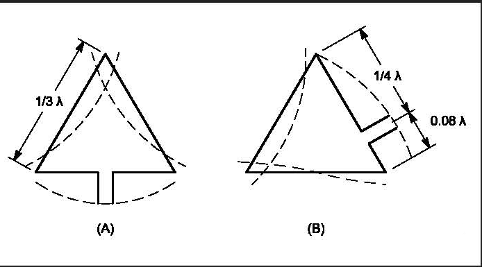
Flip polarazation of antenna horizontal to vertical or vice versa and repeat steps above. Note- Loops A -E have sides approximately 13 wavelength but overall circumference delta loop is the same as an equivalent quad on the same frequency ie. What Size Wire.
1005 FMHz feet or 30631 FMHz metres. A more omni-directional radiation pattern than that of a dipole. Find worst case mode.
Extra Radiation By letting it do so the outer shield of the 22 feet long vertical coax RG-8X radiates to fill in the gaps in the signal pattern radiated by the top portion of the antenna. Orange peel antenna Used in search radars this is a long narrow antenna shaped like the letter C. This is often used in radar antennas.
An antenna with a higher gain is more effective in its radiation pattern. - The radiation pattern is very clear. A lower resonant frequency for the same length of wire as the dipole.
It uses a director element that is built into the dipole assembly to shape the pattern - if you end up with a used one and it is missing the director theres no telling what the final pattern will look like. In any illustration the sketch drawn to represent the radiation of an antenna is its radiation patternOne can simply understand the function and directivity of an antenna by having a look at its radiation pattern. This antenna normally has about a 3 DB gain over a 12 wave center fed dipole.
Antenna projects for 144 MHz category is a curation of 153 web resources on Simple VHF Antenna Magnetic Loop for the 2m band The Tiny 3. Move antenna up and down to find the maximum amplitude of signal. As a general principle the wider the antenna is in a given transverse direction the narrower the radiation pattern will be in that direction.
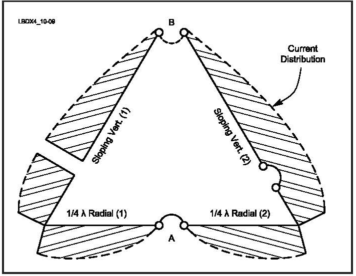
With usual coax of 50 and 75 Ohm the following cases are interesting. A full-size Delta Loop fed in the bottom corner is a good low angle radiator and is great for working DX. The 4NEC2 calculation input output page feed impedance plots a diagrammatic image of the radiated pattern at a distance of 1 kilometre antenna current for an input power of 100 watts vertical gain in dB and finally the loops radiated vertical signal level at a distance of 1 kilometre also for an input of 100 watts.
The NEC output included in this iteration include. The radiation pattern of these antennas will be same as that of short horizontal dipole antenna. Some say that the inverted V should be cut 5 shorter than the dipole.
The DB-225 is a single element 5 dB gain dipole station antenna that provides a semi-circular radiation pattern their term not mine. D eciding to put up a loop antenna can be more of a logistical problem than an engineering. When such a small loop antenna is mounted on top of a portable receiver whose output is connected to a meter it becomes a great direction finder.
A vertical loop may have either vertical or horizontal polarity depending on where you feed it. Omnidirectional radiation patterns are produced by the simplest practical antennas monopole and dipole antennas consisting of one or two straight rod conductors on a common axisAntenna gain G is defined as antenna efficiency e multiplied by antenna directivity D which is expressed mathematically as. The Delta Loop is not only a great transmitting antenna but a low noise receiving antenna.
If its higher than previously seen go back to step two. The 22 feet portion of the feedline effectively becomes an upside down vertical located high above ground and free of ground losses normally associated. Antennas are classified into many types based on their structure like wire type antenna aperture type antenna classification based in types of frequency like very low or high-frequency type antenna microwave antenna etc function capacity dimensions classification based on directions like an omnidirectional antenna radiates power in a single direction a.
Antennas are designed in such a way that power raises in the wanted direction and decreases in unwanted directions. This is a universal truth. The small loop antenna is generally a linearly polarized one.
Some loss in bandwidth. Note that the vertical pattern of a dipole changes radically as height is changed above 14 wavelength or 125 feet on 160 meters or 65 feet on 80 meters. To get more gain an antenna must radiate in fewer directions.
- For shortwave and 6m you can wind the cable to a choke with an additional suppression of sleeve-waves. The sloper certainly has a larger footprint and possibly a significantly different radiation pattern. An antenna will have the same gain when receiving as when transmitting and also the same radiation pattern.
Resources listed under Antenna for 2 meters category belongs to Antennas main collection and get reviewed and rated by amateur radio operators. The antenna can be ground mounted or attached to an insulated pole which will further improve the HF performance as shown later. A useful relationship between omnidirectional radiation.
Construction Hints Tips. Imagine a spherical balloon. 40m-10m DELTA LOOP ANTENNA - GU3WHN The variety of one wave length loop shapes that can be deployed to suit the QTH.
The parameter that measures the degree of directivity of the antennas radial pattern is known as gain. Vertical Quad loops are most frequently fed in the center of the bottom horizontal leg. Used Vertically quad loops will exhibit a figure 8 broadside pattern much like a dipole but with better gain.
Radiation is the term used to represent the emission or reception of wave front at the antenna specifying its strength.

Delta Loop Antenna Radiation Patterns Hy Power Antenna Company

Delta Loop Antenna Radiation Patterns Hy Power Antenna Company

Delta Loop Antenna Radiation Patterns Hy Power Antenna Company

Delta Loop Antenna Radiation Patterns Hy Power Antenna Company
All Band Use Of Vertical Plane Deltas
Delta Loop
Top Band Hams Vertical Loop Antennas
Top Band Hams Vertical Loop Antennas
0 comments
Post a Comment